Electricity (physics NOTES)
The electric potential energy of any given charge or system of changes is termed as the total work done by an external agent in bringing the charge or the system of charges from infinity to the present configuration without undergoing any acceleration.
Definition: Electric potential energy is defined as the total potential energy a unit charge will possess if located at any point in the outer space.
general formula is Voltage = Energy/Charge. the S.I unit is volt.
Let us learn about some of the important components of circuits and their symbols in a circuit diagram.
- An electric cell: It provides the source of current. In its symbol, the larger terminal is positive, whereas the smaller one is the negative terminal.
![]()
- A battery: It is a combination of cells and its utility is the same as the cell.
![]()
- Switch: It is a plug key used to allow or stop the flow of current upon being pressed. It may be an open or a closed switch.

- Wire joint: One device may be connected to the other using wires. This is shown by drawing ‘blobs’ at their point of connectivity.

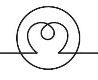
- Wires crossing without joining: The wires that do not touch each other are drawn without blobs. The following figure shows how the unjoined wires are represented.

- Electric bulb: The electrical device which uses electricity to glow.

- Resistor (R): It is used to restrict the amount of current flow in the circuit.
![]()
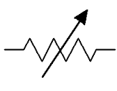
- Variable resistance: Also known as the rheostat, it is used to regulate the amount of current flow by increasing or decreasing the resistance to the current flow.

- Ammeter: It is used to measure the current passing at a particular point.
![]()
- Voltmeter: It is used to measure the voltage between two points in a circuit.

Ohm's law:
Ohm’s Law states that the current flowing through a conductor is directly proportional to the potential difference applied across its ends, provided the temperature and other physical conditions remain unchanged. Mathematically it can be represented as,
( When the value of V increases the value of I increases simultaneously)
Conductors with a uniform cross-section and uniform flow of electric current will have the following resistivity formula:
A circuit is said to be connected in series when the same amount of current flows through the resistors. In such circuits, the voltage across each resistor is different. In a series connection, if any resistor is broken or a fault occurs, then the entire circuit is turned off. The construction of a series circuit is simpler compared to a parallel circuit.

For the above circuit, the total resistance is given as:
For example, consider the following sample problem.
A resistor having an electrical resistance value of 100 ohms, is connected to another resistor with a resistance value of 200 ohms. The two resistances are connected in series. What is the total resistance across the system?
Here, R1 = 100 Ω and R2= 200 Ω
Rtotal = 100 + 200 = 300 Ω
Resistor in parallel:
A circuit is said to be connected in parallel when the voltage is same across the resistors. In such circuits, the current is branched out and recombines when branches meet at a common point. A resistor or any other component can be connected or disconnected easily without affecting other elements in a parallel circuit.

The figure above shows ‘n’ number of resistors connected in parallel. The following relation gives the total resistance here
The sum of reciprocals of resistance of an individual resistor is the total reciprocal resistance of the system.
For the problem given above, what if the resistors were connected in parallel instead of in series? What is the total resistance in that case?
=
=
Therefore,
The heating effect of electric current is widely used in our day-to-day life. The electric iron, kettle, toaster, heater etc. are used as alternatives to the conventional methods of cooking and laundry. The same is used in electric bulbs which is the alternative of conventional lamps. These devices have revolutionized the world over the years. In this section we will discuss the concept of heating effect of electric current and its applications.

When an electric current is passed through a conductor, it generates heat due to the hindrance caused by the conductor to the flowing current. The work done in overcoming the hindrance to the current generates heat in that conductor.
Application of heating effect of electric current:
Following are the devices in which heating effect of current is harnessed for other purposes:
Electric Iron:
Mica is an insulator that is placed between the metal part and the coil in an iron. The coil becomes heated with the passage of current which is then transferred to the metallic part through mica. Finally, the metal part becomes heated which is then used for ironing clothes.

Electric Bulb:
Electric bulb contains a thick metallic wire made up of tungsten metal. The metal is kept in an inert environment with a neutral gas or vacuum. When current flows through the tungsten wire, it becomes heated and emits light. Most of the electric power drawn in the circuit from the electrical source is dissipated in the form of heat and the rest is emitted in the form of light energy.

Electric Heater:
In an electric heater, high resistance nichrome wire is used as a coil. The coil is wound on grooves made up in ceramic material or china clay. When the current flows in the coil, it becomes heated, which is then used to heat cooking vessels.

Electric Fuse:
In any electrical instrument, due to sudden rise of current, the instrument gets burnt down which sometimes results in fire. A conducting wire with low melting point is connected in series with the circuit to avoid this type of accident. When the current rises, the wire melts due to excessive heating, thus breaking the electrical circuit.

For harnessing the heating effect of electric current, the element of appliances is required to have high melting points to retain more heat.
Electric power:
Electric power is the rate at which work is done or energy is transformed in an electrical circuit. Simply put, it is a measure of how much energy is used in a span of time.
Symbol | P |
SI Unit | Watt, joule per second |
Scalar or Vector | Scalar Quantity |
Formula | P=VI |
Formula;
The formula for electric power is given by
where,
P is the power
V is the potential difference in the circuit
I is the electric current
Power can also be written as
The above two expressions are got by using Ohms law, Where, Voltage, current and resistance are related by the following relation
Where,
R is the resistance in the circuit.
V is the potential difference in the circuit
I is the electric current

Power Energy Formula:
Since power is the rate of energy consumption, energy can directly be calculated using
Where,
E is the energy consumption (in Joules)
t is the time in seconds
Where,
- Q is the charge (in Coulombs)
- V is Potential difference in volts
- t is the time in seconds

Comments
Post a Comment